
Help! My Isolator Is Taking Too Long To Degas — What Should I Do?
By Herman Bozenhardt and Erich Bozenhardt
 Probably one of the most significant developments in sterilization and aseptic practices in the pharmaceutical business is that of vaporized hydrogen peroxide (VHP) as a contact or “cold” sterilizing agent. The use of VHP in contained environments has allowed us to decontaminate working spaces, equipment, and materials and has led to the development of the reliable isolator. This application has led to many years of success and provided assurance that aseptic handling and filling operations are microbial-free. In this article we will focus on filling isolator systems and equipment. Since the use of this technology began, we have been singularly focused on sterility by maximizing injection rates and saturation levels and assuring media fills are successful in qualification testing.
Another evolution of this technology is the size, complexity, and diversity of isolators the VHP has been applied to. Originally isolators were “boxes” or “cylinders” with lots of injection nozzles and a simple HEPA exhaust scheme. Today the isolators have increased in size so much that the height and width require more nozzles and greater reach across the fill deck. In addition, we now have isolators with seven to 13 sections, with multiple right angles to adjacent sections where each section can be 10 to 20 meters long, and with several auxiliary docking sections. In all these cases we compensate with more VHP injection because we need to ensure successful media fills.
New Reality
As this expansion of VHP use and isolator complexity evolves, we have driven ourselves directly into the newest class of drug products and have “hit the wall.” We have discovered many new therapies that are classified as “ultra-low” potency products (in the microgram and nanogram per ml), biologicals that are sensitive to VHP (and any oxidizer in the vapor phase) and incompatible products (in some cases there was no prior testing or consideration for VHP interaction). In these cases, the residual VHP vapor in the isolator interacts with the open vial of liquid between the dosing nozzles and the capping station and oxidizes the API in the solution. This becomes a more severe problem with lyophilized products, where the liquid is exposed from the dosing needle through the fluted stopper and into the lyophilizer itself. This has had a major impact on new installations and CMOs as they acquire new business in their legacy aseptic filling isolators. In some cases, the residual VHP has attenuated product by 10 to 15 percent potency in standard fills and up to 25 percent degradation in lyophilized production.
For the CMO, this often violates many of their standard practices and crushes their high confidence in their VHP cycle and media fill, and they must face the reality of many isolator changes and potentially reducing their VHP cycles. This also exposes a flaw: that some isolator VHP residual levels have never been understood, challenged, or questioned. In many cases with low-potency products or biologicals, we need to set the residual level from the 100 +/- ppm levels to as low as 10 ppb. Some may wonder if this achievable, and the answer is absolutely. However, some practices, equipment, and processes need to change, and for the better. We will now explore the process of degassing and removing residual VHP via aeration from the various commercial isolators.
Wrong “Solutions”
As we have dealt with these issues on a global level, we have found folks who think outside the box and approach the problem with more problems:
- “Let’s just fill with a higher concentration.” This approach of concentrating the product and letting the degradation take its toll is foolish. That would require a change to the submission documents and show a lack of study of the compatibility of VHP with the product. In addition, the oxidation of the API produces a compound, and now we would have introduced a new impurity. The FDA would be very interested in this.
- “Let’s increase the fill volume.” This is equally inappropriate, as the same issues as above will occur, with a degraded potency and more volume. The residual generated will be questioned, as will the manufacturing submission.
- “Let’s just HEPA-ventilate until we get a good reading.” While this is a compliant solution, it results in a degassing that could take days or weeks to accomplish. This could have a devastating impact on product delivery and plant capacity. By using excessive fresh air ventilation, we are also stretching the service life of the internal HEPA filters while increasing the operating cost geometrically. The air handling unit (AHU) and cooling costs will drive up the power load.
- “Let’s see if we can cut back on the validated VHP cycle and see what happens.” This is a risky approach, since any change to the process would require a change control and re-execution of media fills. Without any engineering changes, this is a gamble at best.
The Best Solution
- Recognizing VHP and its residual exist and could impact the product is the first step in avoiding a problem. It is important to use the product and run VHP compatibility tests, challenges, and fill trials to gather data and understand the impact before the fill is tech-transferred into the isolator site/environment. This should be done in a pilot plant or, at worst, in a “development” mode with the isolator. This would allow data to be gathered, a judgement reached on impact, and a rational design executed before the fill tech-transfer. This would provide parameters for the residual ppm or ppb of the VHP, the degassing time, and any field-based modifications needed (options below). The careful design of the cycles (both VHP and degassing/aeration) and understanding the VHP levels, temperatures, relative humidity, velocity of aeration, air change rate (ACR) in the isolator, and point HP values via instrumentation is invaluable. A virtual 3D model of the residual VHP generally allows pinpointing the key VHP source. This proactive approach saves time and money and allows for the selection of a best economic solution, which is a tradeoff of engineering technologies and degassing time.
Field-Based Solutions
- One of the most common and overlooked problems is liquid pooling in certain areas above and below the fill deck. However, you will never see this at the brief factory acceptance test (FAT), but after several in house VHP runs a gasket, opening, port, or other point allows moisture collection and it will contain dissolved HP. A careful study of the unit during and directly after the VHP routine (of the equipment, the deck, and below the deck) is usually the first step in troubleshooting.
- The next key area to look for is the elimination of polymer-based materials inside the isolator, especially all platinum-cured silicon tubing. All polymer-based material absorbs VHP during the cycle and slowly expresses it, but at a rate that will continue to thwart the degassing. Some polymers are significantly worse than others. The focus is to maximize stainless steel and use Teflon, polyethylene, and polypropylene only when required. The most detrimental and absorptive polymers are Delrin, polyurethanes, polyamides, polysulfones, and polystyrenes. You must look carefully at the materials of construction of your tubing, filters, seals, gaskets, and other polymer-based components. This also includes the HEPA filters and mounting systems. The user needs to understand the materials in the HEPA filter frames particularly. In some CMOs, the isolators have HEPA filters on the return ducts/plenums. This is to prevent cross-contamination; these filters (polymers) can be removed if the product profile does not contain cytotoxics, potent compounds, or active biologics.
- Along with the polymer-based investigation should be a careful review of the gloves, glove ports, and other interface seals. First check for materials of construction, and then make sure the gloves are all extended (fingers are not together) and have no obscured surfaces or cover a port of another polymer seal. Polymer surfaces trapped against one another can also trap and retain VHP and interfere with normal aeration/degassing.
- The isolators have AHUs that control the air circulating from the isolator deck-level returns. These AHUs have cooling coils to control the temperature in the isolator section, which is primarily a cooling function. The coils are fed chilled plant water internally to cool the air drawn by the blowers, which pushes the air through the HEPAs back to the isolator for downward coverage of the vials. Since the AHUs are a major operating-cost contributor, they have been optimized for cost savings and minimum circulation and not for degassing. Rethinking design and orientation are needed to service contemporary product lines.
The coils are cold during normal operations and remain so during the VHP cycle (even if the chilled water supply valve is shut). The coils are an ideal place for water to condense, collect, and retain HP (dissolved hydrogen peroxide). Once pooled in this area, it could take days to evaporate the water and the HP. This is one of the most prevalent problem areas.
In order for this area not to pool liquid and become the HP reservoir for the unit, the control system must condition the isolator coils for a post-batch/pre-VHP cycle. In some designs, there is no temperature control unit (TCU) for heating and the valves control the chilled water going into a recycle mode and slowly let the heat from the isolator and machinery warm the air stream. In a more contemporary design (see AHU scheme), a TCU provides either plant hot water or electrically heated water to elevate the temperature of the coils and the internals of the isolator.
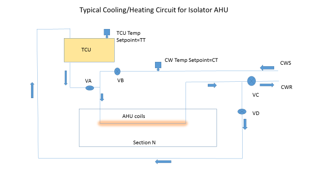
In this case, during the normal isolator-filling scheme the programmable logic controller (PLC) controlling the isolator AHU has a chilled water (CW) set point CT that has valve VB controlling the chilled water circulating (valves VA and VD are closed, and VC is open 100 percent). To prepare for the VHP cycle, the PLC needs to increase the temperature of the coils above the condensing temperature of the VHP (remember the coils and blower are upstream of the HEPA filters). This temperature should be 35 degrees Celsius and should be attained quickly. This will require a TCU to come online with its pump, shut VB and VC and open VD 100 percent, and control the temperature by actuating valve VA and putting the TCU mode to heat.
The next step is to run the isolator VHP cycle, knowing the coils are heated. Once the VHP cycle is completed, the degassing should reinitiate the coil-heating cycle and drive the temperature of the entire isolator up and accelerate the degassing, making sure any residual VHP and water/HP evaporates quickly.
As in all of these types of applications, a detailed time-based analysis of the PLC cycle is critical, as an inadvertent activation of a chilled water line, a wrong set point for a short period of time, or a valve sequenced incorrectly could be the root cause of the AHU problems.
- One of the most worthwhile investments in an isolator is the VHP/HP absorbing catalyst that can be installed in the AHU. These catalyst systems are ideal to quickly absorb the VHP from the isolator during their recirculation mode. The key to efficiency of the isolator is its ability to recirculate air and only bleed in “make-up” air. The catalyst needs to be placed by catalyst experts in coordination with the isolator manufacturer for the correct location, air velocity tests, PLC sequence of when to engage the catalyst, and overall commissioning of the unit. This allows the isolator to run in its most efficient (re-circulation) mode and absorb/destroy VHP. This is ideal if it is done in the design of system. If this is done as a retrofit, the isolator will be taken out of service and should be re-commissioned, and re-execution of the media fills would be required.
- Fan circulation of fresh air and recirculated air is another consideration. As mentioned above, the isolator typically runs in the mode of recirculation and reduced power consumption. The blowers are generally variable frequency drives (VFDs), and the PLC controlling them may not be programmed properly for maximum exhaust. The blower-controlling part of the PLC must insure the fans are in sync, not inhibited by the power management scheme, and able to generate an exhaust profile that flushes the entire isolator section. It is important to understand the fluid dynamics in the isolator, not only during the VHP cycle, but the degassing cycle as well. These are different cycles with different objectives, and while dwell time and distribution are key for the VHP injection and downward velocity of .36 to .45 m/s are key for filling, they do not necessarily work for the degassing/rapid air egress. The only way to assure ourselves the isolator is being degassed, not leaving “dead zones” or creating vortices that recirculate the air or another anomaly, is to perform a computational fluid dynamic (CFD) model of the isolator. We have too many situations where inadequate air turnover and dead zones are caused by equipment position, filling deck height, fan location, and areas not evacuated cleanly. This can also be true of the many “docking station” options. In the end, your understanding of the air velocities, aeration profile, and delta pressure across constrictions is key.
- An alternative that is very effective, and also expensive, is the retrofitting of the filling system with a nitrogen “blow” into the vials, nitrogen backfill at dispense, and nitrogen blanket up to the stoppering zone. This does not improve the degassing; however, it protects the product up to a level. If done at the isolator design, the incremental cost is well contained. However, if done as a retrofit, it can cost several million dollars and delay operational use by a year. Another consideration is that relying on a nitrogen headspace to protect the product will impact the regulatory filing, as a new ingredient has been introduced.
In summary, troubleshooting of a degassing/aeration problem of an isolator requires a substantial amount of time, analysis, and patience. To reduce a VHP level in an isolator from 50 ppm to 50 ppb could take months. That is why nitrogen backfilling plus isolator CFD analysis, polymer elimination, and careful temperature control can mean the difference in over a year of startup time and higher capacity throughput.
About The Authors:
 Herman Bozenhardt has 42 years of experience in pharmaceutical, biotechnology, and medical device manufacturing, engineering, and compliance. He is a recognized expert in aseptic filling facilities and systems and has extensive experience in the manufacture of therapeutic biologicals and vaccines. His current consulting work focuses on the areas of aseptic systems, biological manufacturing, and automation/computer systems. He has a B.S. in chemical engineering and an M.S. in system engineering, both from the Polytechnic Institute of Brooklyn. You can reach him at hermanbozenhardt@gmail.com or connect with him on LinkedIn.
 Erich Bozenhardt is the process manager for Integrated Project Services’ process group in Raleigh, NC. He has 12 years of experience in the biotechnology and aseptic processing business and has led several biological manufacturing projects, including cell therapies, mammalian cell culture, and novel delivery systems. He has a B.S. in chemical engineering and an MBA, both from the University of Delaware. You can reach him at ebozenhardt@ipsdb.com or connect with him on LinkedIn.
Isolator image courtesy of ProSys