
Are You Overlooking This Critical Component Of Bioprocess Facility Design?

By Herman Bozenhardt, Bozenhardt Consulting Services, and Erich Bozenhardt, IPS-Integrated Project Services
Expansions and renovations to existing biological facilities, and construction of new facilities, provide a unique opportunity to rethink basic design strategies and use new technologies to build a better facility that will improve compliance. This article is the fourth in a six-part series on how single-use systems are changing the modern biotechnology facility and process design paradigm.
As discussed in a previous article in this series (An Introduction To Biopharmaceutical Facility Design & Layout), there are multiple variables that must be considered in the layout of a biopharmaceutical facility, and many of these variables are interdependent. This article will explore a critical but often overlooked component of bioprocess facility design — HVAC systems — and the realities of HVAC compliance and methods. HVAC is the single continuous and active system that removes the bioburden and particulates introduced by the facilities’ single most contaminating source, humans!
Key Concepts: Air and Bioburden
HVAC is closely aligned with architectural layout, and it is the operational key to any biopharmaceutical facility. HVAC is the only continuous and active system that removes bioburden and provides a barrier between people and equipment. The HVAC system should provide:
- A straight laminar air blanket vertically across all equipment to suppress particulates and bioburden,
- An air curtain that separates the source of particulates (humans) from any exposed product or process,
- The means to pressurize, segregate, and contain airborne elements in a specific architectural area, and
- The means to constantly sweep the air space and physical surfaces, and to capture and remove particulates and bioburden in the HEPA filters.
HVAC design needs to incorporate the engineering requirements of isolation, segregation, pressurization, and distribution to arrive at an optimal solution. Physical layout, supply and return register locations, and air change rate (ACR) are some of the general parameters we must use to achieve an effective design. We must also embrace the tool called CFD (computational fluid dynamics) to visualize the HVAC solution in our key suites.
Our discussion will focus on high-level design concepts and features process designers need to know. A major word of caution here: One prevailing notion in the industry is that with single-use systems (SUS), HVAC design has become irrelevant. This attitude has resulted in poor compliance, systems that cannot be validated, and poorly constructed facilities that do not meet any of the EU grade classifications. HVAC is still very relevant, as FDA and EU inspectors will remind you! Specifically for SUS and other closed systems, the HVAC classifications set limits for particulates and bioburden, so these systems can be validated against relevant challenges.
Regulations and Standards
The current standards for regulations are actually very clear in terms of what is required for each operational grade used in biopharmaceutical manufacturing:
- Grade A, for bulk and aseptic filling, requires ISO 5 for both operational and at-rest conditions.
- Grade C, for bulk compounding, requires ISO 8 for operational conditions and ISO 7 for at–rest; therefore, we design to ISO 7 conditions.
- Grade D, for bulk compounding, corridors, and background for specialized processing, requires ISO 8 at rest, and we design to ISO 8.
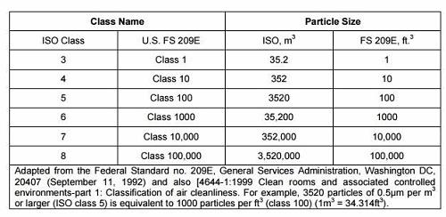
To illustrate the requirements, Table 1 below shows ISO 14644and equivalent U.S. Federal Standard 209 E (FED-STD-209 E) classifications for particulate levels. Note: FED-STD-209 was cancelled by the U.S. General Services Administration (GSA) in 2001 and was superseded by ISO 14644 standards.
Table 1: ISO 14644 and Corresponding FED-STD-209 E Cleanroom Classifications
It is important to point out that particulate counts are a result of the design and do not constitute the entire requirement. As you can see in Table 2, there is substantially more to understand when designing the HVAC system. Air change rate, downward velocity, and percentage of ceiling coverage are also parts of the compliance/design puzzle. It is critical to have a reflected ceiling plan that provides the percent coverage, as well as a symmetrical placement of both supply and return registers for consistent flow characteristics.
Table 2: ISO 14644-1 Requirements for Cleanrooms

All design aspects allow for some flexibility to achieve the goals; however, designers often focus on the absolute minimum of all the aspects shown in Tables 1 and 2. This approach always fails to meet the necessary criteria. We recommend erring on the higher side with percentage ceiling coverage, and then adjusting your design parameters to meet the remaining design goals midpoint. All biopharmaceutical startups are plagued by air balancing and demand problems. A small amount of overdesign in this aspect will provide startups with better long-term performance as the system (HEPA filters and air handling units) ages into full lifecycle.
Important HVAC Methods
In the following sections, we will discuss the key engineering concepts that should be addressed in every biopharmaceutical facility design.
Isolation
In Bioprocess Facility Design — Layout Rules And Configurations, we discussed the concept of “isolating” processes and/or production to provide containment. Containment of process — based upon risk assessment, biosafety (BSL) level, viral vs. non-viral, or any of many others — focuses on keeping all the process components and materials within one architectural suite. This is necessary for two reasons:
- To contain products, media, and components of a product, preventing them from contaminating any other suite
- To prevent any bioburden outbreak that might occur in one suite from traveling into another suite, whether similar product or not. Isolation facilitates quick identification and remediation, and prevents plant-wide contamination.
Isolation is accomplished using architectural barriers of walls and ceilings, but it must also incorporate HVAC and pressure gradients to push airborne particulates within the suites as doors are opened and closed. Figure 1 below shows a brief illustration of air sinks (yellow circles) and air bubbles (green circles), which isolate a suite from other suites.

Figure 1: Sample facility configurations incorporating air sinks and air bubbles
In this example, the process suite is pressurized and sends all its air leakage into either the personnel airlock (PAL) or material/equipment airlock (MAL), due to the pressure gradients caused by the air supply/return design. The corridors likewise are pressurized to send air into the airlocks. This airlock now becomes an air sink. This scheme prevents airborne dirt/particulates from the corridors from entering the process suite, while simultaneously keeping the airborne elements of the process suite from entering the corridor and contaminating people, raw materials, finished goods, or equipment. This scheme is essential for all multi-product facilities. In summary, it prevents cross-contamination across the manufacturing complex.
Alternatively, the air bubble concept by design over-pressurizes the PAL and MAL to blow/leak air into both the corridor and the process suite to isolate it and provide similar protection. There is always controversy about which is the best scheme to implement — air sink or air bubble. The deciding factor should be the fail-safe situation, when any one AHU fails. Another consideration is the over-pressure of the MAL or PAL and what is performed in that airlock. If cleaning of equipment or bag stripping is conducted in the airlock, foreign particulates and bioburden can pressure over into the process suite. As a rule of thumb, the air sink concept should be used when concern for particulates and bioburden is a major risk factor.
Figure 2 below shows an example of the newest scheme for handling a potent compound or a toxin. Note that the leftmost diagram shows the air sink concept built onto the MAL/PAL airlock in a second level of isolation. The design for these potent compound suites requires sufficient air supply and an even greater number of return registers for the MAL/PAL/air sinks. MAL/PAL/air sinks have become a cornerstone for compliance and risk reduction. This shows how designs have evolved from the days when airlocks were treated more like vestibules for gowning.

Figure 2: Recommended vs. legacy configurations, showing a second level of airlock isolation
Segregation
Segregation is a separate design concept from isolation. However, the two methods become unified in developing the design of AHUs. Segregation is the aspect of separating the facility’s AHUs, depending on risk assessment. That risk assessment centers on the impact of the failure of any one AHU (blower/chiller coil/filter bank). Designs should ensure that such a failure will only affect one major processing suite or one product in a multiproduct facility. This concept is inclusive of all the supply and return registers, as together they form an AHU unit. Bundling AHU supplies for several suites defeats the concept, and combining return registers will destroy the air balance and force contaminants from one suite into the AHU return plenum of another.
In our examples in Figure 1, if the AHU for the process suite fails, the AHU for the corridor keeps the pressure on and does not allow the airborne material from the suite into the corridor. And if there is a spill or bioburden excursion, it is contained in that one suite. This also allows all the other parallel suites to continue manufacturing and assures there will be no cross-contamination. This configuration naturally focuses the design on having separate AHUs for each major suite or product train. This meshes with the various commercial configurations we covered in our last article, and drives designs to use smaller, less-expensive variable frequency drive (VFD) based AHUs, instead of the larger AHUs of legacy plants.
Segregation also must address the potential use of each suite and the need to prevent the AHU itself from becoming contaminated. Toxins, potent mAbs, or other materials can be swept up into the return registers of the AHU and expose those working on the AHU to potentially dangerous contaminants. In such cases, those AHUs need to have HEPA filters at the return registers as well as at the HEPA supply. This HEPA in and HEPA out design uses a BIBO (bag in/bag out) device. All BIBO must be accessible from within a controlled suite that can be decontaminated, and should never be located in a mechanical space or outdoors.
In the area of a BSL design, the U.S. Centers for Disease Control and Prevention (CDC) requires the use of redundant AHUs for the highest level of BSL; however, the industry typically designs and builds in redundancy for each BSL level. This must be considered as a major factor in AHU risk assessment.
Pressurization
Pressurization focuses on the various suites for production and the potential paths of bioburden, products, raw materials, and particulates. In a plant with non-potent products, minimum open processing, or a single product, a positive pressurization scheme can be employed. In this scheme, the innermost suite of the manufacturing train (or the core of the process, e.g. bioreactor/harvester) has the highest pressure (EU Grade C), and the next suite/room has .05 inch of water gauge (iwg) less, and so on until it terminates in a CNC (controlled non-classified) area. This forces the innermost suite to have the highest pressure and highest air flow. This scheme could potentially contaminate one suite with another’s product or bioburden.
Pressurization also works in the opposite manner when dealing with potent compound or toxin. The pressurization is the most positive in the CNC area and the .05 iwg deceases as we work our way inward to the central core. This scheme does protect the toxic material from escaping out into the unclassified environment. In this scheme, we could potentially contaminate the process core with bioburden or contaminants from the CNC.
In summary, the air sink or air bubble concepts are the dominant design philosophies to form a pressure layer/pressure break between EU grades.
Distribution
Air distribution within any suite/cell or manufacturing space must be carefully designed and planned out. Following are rules to follow when planning air distribution:
- Air distribution within any room must be designed to provide symmetrical coverage over the equipment and personnel, and should not be left up to a field HVAC installer. See Figures 3 and 4 for plan and coverage concepts.
- Air distribution must be designed after the process vessel/equipment/piping and interior fit is confirmed.
- Using 3D CAD design to control the utility interaction/HVAC space contention is a must today as we consolidate interior spaces and reduce plant footprints.
- HEPA air supply must be ceiling-mounted with the proper diffusers to provide a laminar flowing air “blanket.” Computational fluid dynamics (CFD) should be used for key suites to calculate the coverage, direction, and velocity. CFD provides images of air flow dynamics, demonstrating air contours that would only be identifiable through smoke studies. Figure 5 is a good example, showing a number of problems in a legacy suite layout and HVAC supply/return scheme. The most serious is the mid-room “swirl” where the high velocity of the supply causes the air stream to strike the floor, sweep up the resting particulates on the floor, and “bounce” up into a circulating vortex of particulates, never to be removed.
- The terminal HEPAs or supply registers must consistently force particulates down around all the vessels and work surfaces based upon the ISO design parameters.
- All HVAC must be ceiling supply.
- All HVAC returns should be floor level returns, integrated with the flooring and termination of the walls. There is no need for floor register grills.
- Biosafety cabinets, tables, and flat equipment are challenging to HVAC design, as they block air flow, cause dead zones, and create their own air path or vortex.

Figure 3: Process suite layout – aerial view

Figure 4: Supply coverage – aerial view

Figure 5: Computational fluid dynamics (CFD) of a legacy core suite about to be renovated by an engineering firm (courtesy of IPS-Integrated Project Services and M/E Engineers, PC, The CAES Group)
The Last Word
Some final recommendations regarding HVAC planning in biopharmaceutical facility design:
- HVAC needs to be highly automated with an integrated SCADA/archive system to troubleshoot problems.
- Delta P and air flow monitoring/trending is key for managing HEPA loading/spikes (HEPA leak).
- The industry is increasingly using HEPA redundancy and UV in the AHU to contain longer-term problems.
- Predictive maintenance via 3D vibration monitoring of AHU drives (VFDs) can eliminate unscheduled shutdowns.
- Implementation of “fan walls” provide for better control, fault tolerance, and lower cost.
- Air leakage under doors must be controlled with seals and is never part of the return scheme.
- HVAC should sweep the floors with a mild horizontal air current and uptake particulates into the AHU returns.
In summary, HVAC design is a complex iterative process that can only begin after the process schema and layout is complete — and in coordination with the architectural practice. HVAC plays a key and active role in bioburden elimination, product protection, personnel protection, regulatory compliance, and containment. Properly designed and constructed, the HVAC system is the most critical and proactive utility in a biopharmaceutical facility.
Future installments in this series will explore how single-use systems can reduce footprints and enable closed systems to drive changes in HVAC (heating, ventilation, and air conditioning), utilities, and construction. Previous articles include:
- Implementing Single-Use At Bioprocessing’s Core
- An Introduction To Biopharmaceutical Facility Design & Layout
- Bioprocess Facility Design — Layout Rules and Configurations
About The Authors
Herman Bozenhardt has 40 years of experience in pharmaceutical, biotechnology, and medical device manufacturing, engineering, and compliance. He is a recognized expert in the area of aseptic filling facilities and systems and has extensive experience in the manufacture of therapeutic biologicals and vaccines. His current consulting work focuses on the areas of aseptic systems, biological manufacturing, and automation/computer systems. He has a B.S. in chemical engineering and an M.S. in system engineering, both from the Polytechnic Institute of Brooklyn.
Erich Bozenhardt is the lead for IPS-Integrated Project Services’ process group in Raleigh, NC. He has 10 years of experience in the biotechnology and aseptic processing business and has led several biological manufacturing projects, including cell therapies, mammalian cell culture, and novel delivery systems. He has a B.S. in chemical engineering and an MBA, both from the Univ